Research & Development Facility
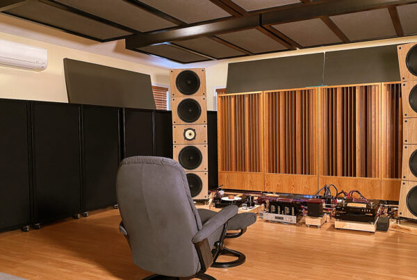
Dennis’ Rig
In this project, we're going to take a closer look at our unique 2-channel setup at the Acoustic Fields R&D facility.
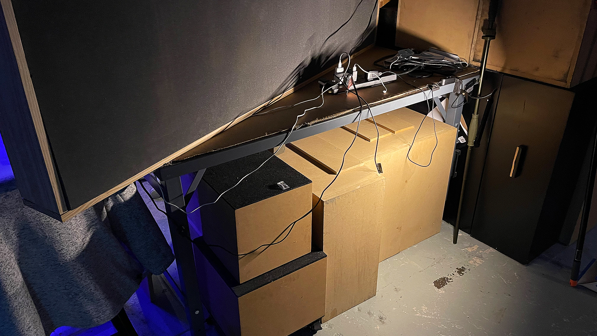
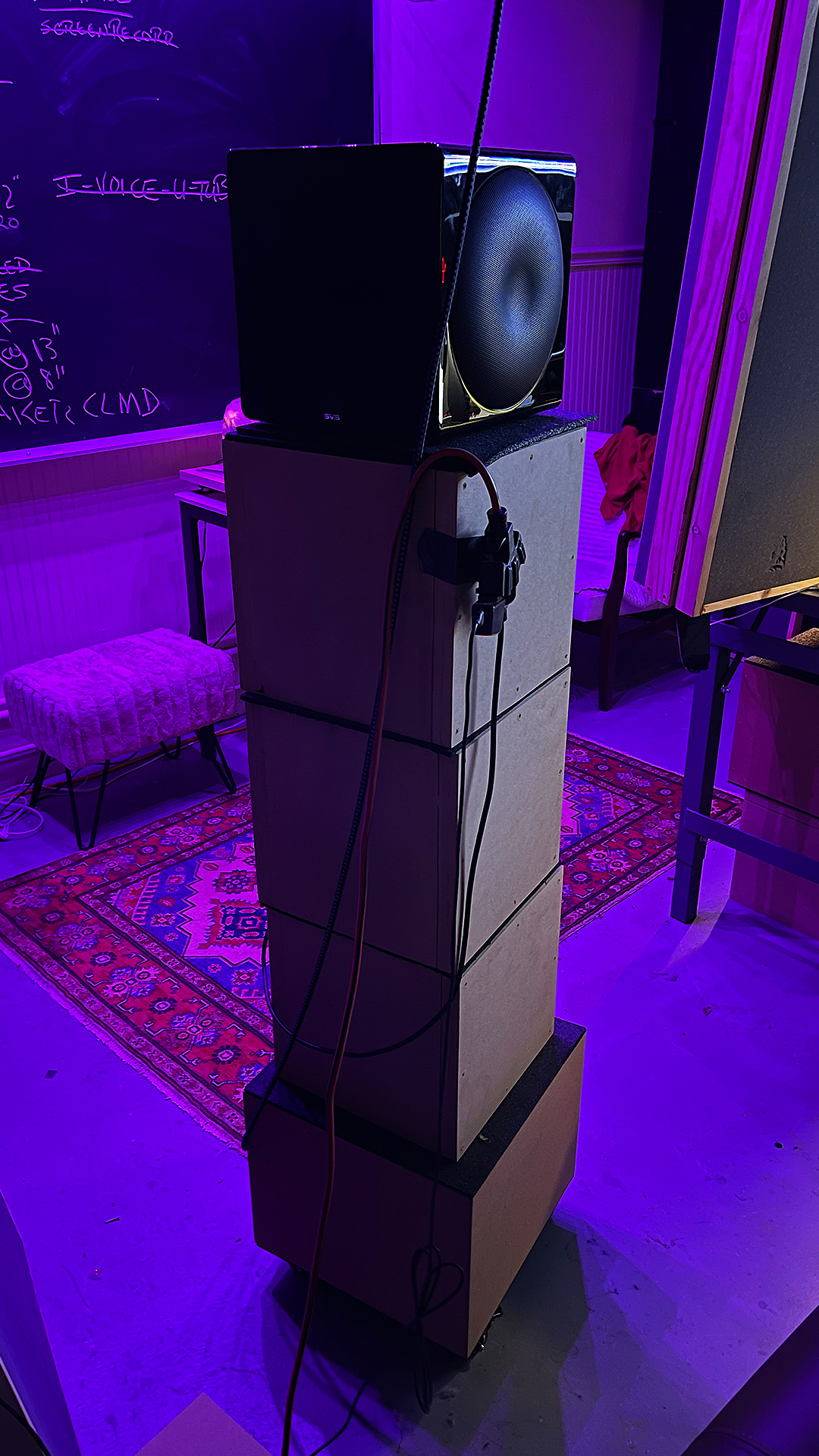
On the other side of one of the short walls in our new test facility for multi-channels, lies my 2 channel rig.The rig sits upon steel tables that can support 2,000 lbs. It is a near field setup using horns. Horns provide a wide dispersion sound pattern. When you test for ways to manage lateral energy produced by two channels to further highlight the benefits of two channels, this large lateral array of energy goes a long way to assist you in the understanding of sidewall primary, secondary, and tertiary reflected energy. Sources are through a computer USB port into a solid state DAC with switchable tube circuitry. A six band switchable I/O EQ can accept the DAC signal and send it onto the active speakers. All cables are upgraded except power. I have one 8″ sub with digital iphone control of EQ curves along with gain and phase.
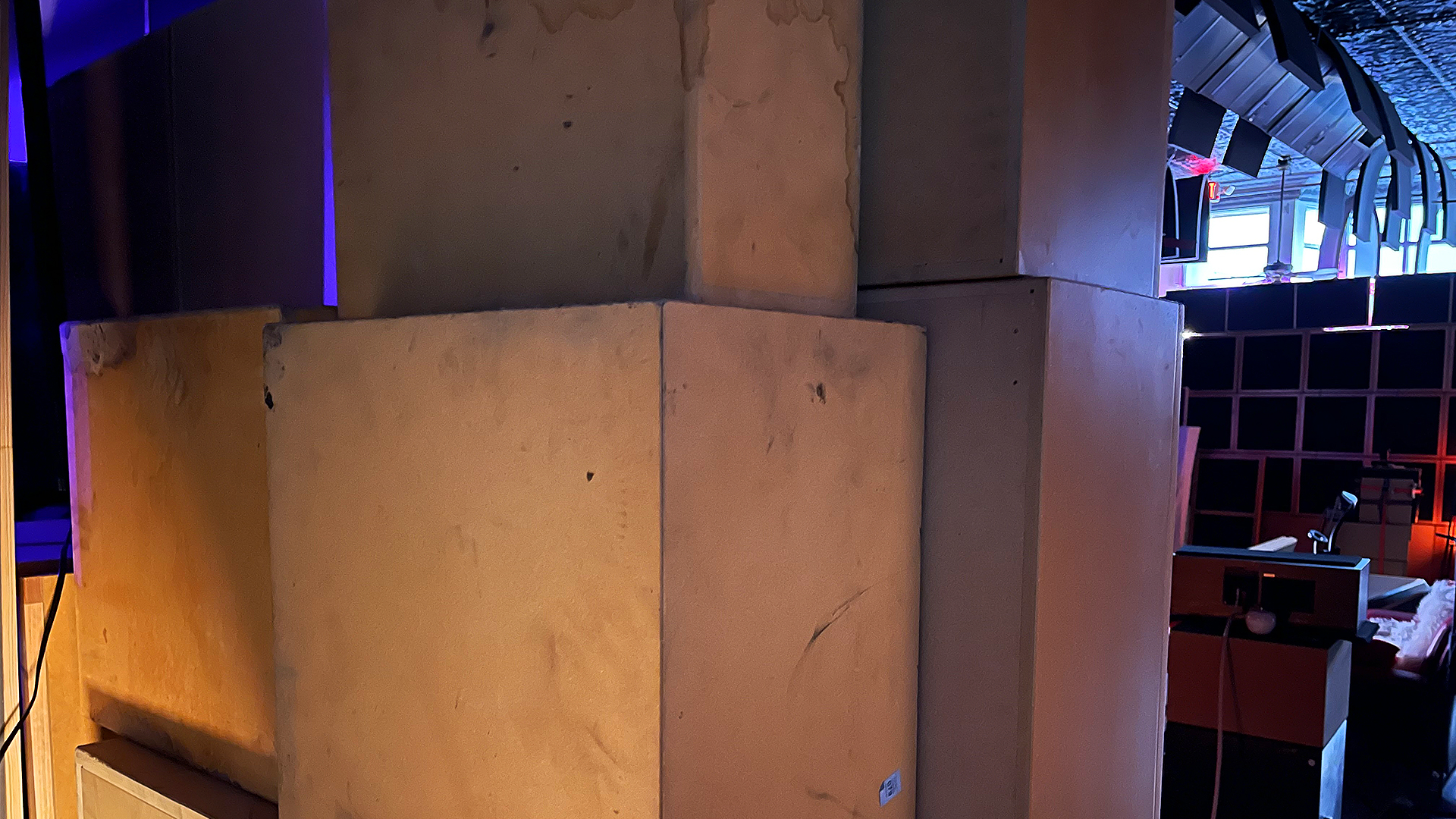
The sub sits on a 5′ high platform composed of stacked module units. Low-frequency front wall treatment is 24″ thick since we have two room walls next to each other. The front wall of my rig is the sidewall of the theater. The theater wall goes up 10′. The rig front wall goes up 6′. The bottom 65% of the wall is 24″ thick. Under the steel tables, we have a combination of our ACDA-10 and 12 modules that are custom built. The sides of each unit come off for easy testing of different thicknesses of our carbon filter system we use inside all of our diaphragmatic technology. Remember, it’s all about having enough surface area coverage at the proper rate and level of absorption. You need the ability to be able to alter the square footage of coverage and the rate of absorption inside that square footage parameter.


Design Goals
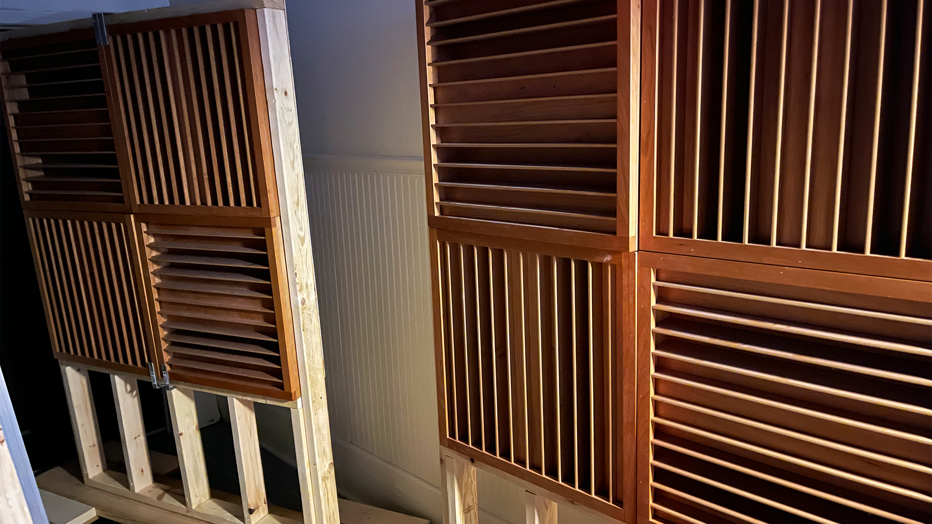
The sidewalls are our foam technology. We have been testing three thicknesses starting with 2″. We tested for a few months. We then moved to a 4″ thick sidewall and now we are at 6″ of thickness for our foam technology. We will report those findings in upcoming videos. We are focused on 125 – 500 Hz. which were the design parameters for our foam. Our foam took me 8 years and 2M to achieve that 125 hz. – 500 hz. absorption rate and level curves. Rear wall diffusion is managed by two QD-7 two dimensional diffusion arrays positioned across the rear wall surface area. Our full sheets of foam are used for rear wall absorption testing. Both technologies are on wheels and can easily be moved in and out of space.
Our design goal is to predict with greater accuracy the square footage requirements of our carbon and foam technologies to ensure certain room resolution parameters. We are focused upon 60%,70%, and 80% room resolution solutions. We have found that these are the resolution ranges that most work within. A mastering room would require a 90% solution. The great thing about our two channel testing area is that the square footage requirements that we achieve for those percentage room resolution requirements translate from our near field set up to larger room sizes and volumes. When you fill out your room forms and we talk on the phone, I will be better able to provide you with the required unit numbers to achieve a 60, 70, and 80% room resolution.


Products in this project

ACDA-10 M
The ACDA -10 modules are our highest performing product. They follow the absorption coefficients of the ACDA-10 with a stronger emphasis on the 60 – 80 Hz. range. The full range absorption for each module is 30 Hz. – 6,500 Hz.
This increased performance comes in a module that is 24″ x 24″ x 12″ and weighs 70 lbs. Modules are stackable and the number and surface area coverage can be fined tuned in your room size/volume/usage.
Find out more

P-13 M
The P-13 M modules are based upon prime number 13 and are 24″ x 24″ x 12″. They weigh 35 lbs each. They stack easily upon the ACDA-10 modules. They can be positioned either horizontally or vertically or both creating a two dimensional diffused sound field if desired. The P-13 M units are built from cherry wood which is the finest wood choice for middle and high-frequency tone and timbre quality.
Find out more

Foam Ladder
Air movement across both sides, reduces the amount of units and surface area required within rooms to reduce the energy level of the reflection. The vertical or horizontal orientations allow you flexibility in positioning the units to fit into existing room aesthetic and space requirements. Mounting hardware is provided. Our foam ladder, is a wood framed unit that surrounds our full sheets of our 2″ thick foam. It measures 57″ x 3″ x 77″
Find out more
More videos from our R&D Facility
Do you want to solve your room acoustic problems?
There’s no one size fits all when it comes to room acoustics.
Get your FREE personal room acoustics analysis by chief acoustics engineer Dennis Foley.