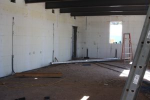
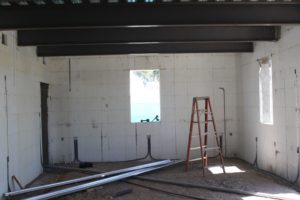
Building a listening room from scratch or as they say in the construction business from the “ground up” is the best way to eliminate any acoustical issues from the drawing phase through the build out. The most important single variable in the drawing phase is the room’s dimensions. Choosing the correct room dimensions from the beginning will save time and money as we go through the project and at the room’s finish. The correct room surface boundary distances and the total room volume can give us a room that requires little or none low frequency issues. And low frequency energy and the resonances they produce in our rooms is and always will be our largest acoustical issue.
How We Picked The Size
What is a best room size? First, we must decide on the end use of the room. For the living roof project, the individual wanted a frequency response that was flat from 20 Hz. – 20,000 Hz. for home theater playback. To achieve this, we have an ideal set of measurements: 30′ W x 50′ L. To be absolutely sure we have a flat response at 20Hz., we really need to have a room dimension of 56 1/2′. This allows a twenty cycle wave to run full cycle and term. We don’t need to use 1/2 wavelength theory when we have 56 1/2′. Our friend decided that he had room for a 50′ room length. At 50′, we are flat down to 22.6 Hz. Everyone on the project was happy. How about the room width?
We need at least 30′ in our width to apply half wave theory, so we get down flat to 20 Hz. at least in theory. Not applying half wavelength theory, we can get down to 37.7 Hz. The site that was chosen allowed for us a maximum foot print of a 25′ width. This gives us a full length wave run of 45 Hz. We decided on the 25″ width because of lot size limitations, knowing if we needed to, we could treat the inside of the room with built in activated carbon low frequency absorption at the room’s pressure areas. We all decided that adding any low frequency absorption to the room, we would look to the floor and wall construction to build it into since our room size and volume was on our side.
Noise Control
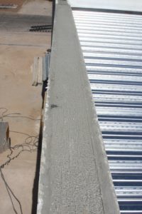
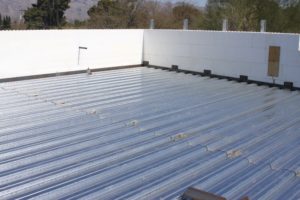
Sound isolation technology just fell into place. The vertical load bearing requirements for the roof needed a certain structural mass for support of the living roof’s very heavy, 18″ of top soil. Structurally, we needed load bearing support all around the perimeter. It just so happened that an 8″ solid poured concrete wall all around would provide the structural support needed at room boundaries for the “living roof”. An 8″ poured concrete wall gives us a STC, sound transmission class, rating of 56. Our goal after time noise measurements was an STC of 62 – 65. We were well on our way. With 18″ of top soil eventually on the roof, we could now turn our attention to the four wall surfaces that will influence the internal sound of the home theater room.
Electronics Set Up
The theater will be set up across the 25′ room width. The 50′ length will run past the listening position. Initial screen to viewing area distances are at 17′ – 20′, with all three front channel speakers a minimum 10′ away from front wall. Side channel and maybe rear channel speaker locations to be determined later. Three sub woofers will provide, hopefully enough low frequency energy for the room volume. We will use a blend of 12″, 15″, and 18″ sub driver diameters. It will be interesting to hear how different size drivers sound in a room that just by its physical size and volume can handle low frequency waves. We will start with sub woofer positions at mid long wall, mid long wall, and mid rear wall. Each sub woofer will be elevated up to a different height from the floor, starting at 18″ and moving through 40″.
Interior Walls
Each interior wall surface will have to be treated acoustically first to deal with any acoustical anomalies and then secondly to achieve the proper blend and balance of wall reflections with direct sound at the viewing/listening seating. The 25′ width walls will each receive some activated carbon absorbers to compensate for a small amount of resonance at lower frequencies. The 50′ long walls will receive a frame supported 4″ thick MDF surfaced wall. Remember, our room size is 25′ x 50′, so we do not have any real, low frequency, resonance issues. However, since we have gone this far with our room, we should make sure all resonances or possibility of them are dealt with at the beginning.
Ceiling Gone
Since it is a home theater room with a large footprint and 12′ high ceilings, we want a surface treatment that acoustically removes the ceiling from our home theater presentation without calling attention to itself both from appearance and performance. Ceiling room treatment must be not seen or heard. To accomplish this, we all agreed on a blend or balance of quadratic diffusion and absorbing foam technology layer throughout. If we use absorption technology for the side walls, which will give us a defined sound stage, we can afford acoustically to put some air back into the sonic presentation using diffusion technology. We don’t want too much and with the large surface area of this room ceiling, we want absorption to handle some of the excess diffused energy at the listening position with a surface area that large.
Side Walls: Absorption
Side walls will be treated with sound absorbing foam technology. Two different foam thicknesses will be used throughout the side walls beginning in the front wall corner and extending past the listening position. This will give us a smooth rate and level of side wall absorption at the listening position, so we can control the energy generated from 6 1/2′ speakers. Our goal at the listening position is for more direct sound which is the straight line sound from your speakers to your ears than reflected sound from our room boundary surfaces. We need some reflections to generate spaciousness within the direct sound presentation from three mono (each) sound sources in our home theater electronics chain, but not as many reflections as we need with a two channel system.
With a room that is 25′ w x 12′ h x 50′ l, with 8″ poured concrete walls and 18″ of top soil for a roof, what more could we ask for? Someone pinch me please. More in part II.
.

