
Since this blog’s initial posting new information and technology regarding quadratic diffusion has emerged, we will reflect on some of those changes withing this updated blog. Update occurred on 02/27/22.
Three things and only three things happen to sound energy. Sound energy is absorbed, reflected, or diffused. Absorption converts sound energy to heat and then sound energy is lost forever. We have to be careful about losing energy in order to manage it in our small room acoustic situations. Reflections are always with us from our room boundary surfaces and have a negative impact on sound and speech intelligibility. Quadratic residue diffusers can be one method of dealing with reflections Diffused sound, using quadratic residue diffusers takes a conscious design goal to achieve proper results.
5 Quadratic Diffuser Build Plans Included In Our All-In-One DIY Bundle!
Meet the most advanced DIY acoustic treatment plans online! They include 5 sound diffuser build plans, 1 bass absorber build plan, and 1 acoustic panel plan. Developed by an industry leading expert, these plans offer the most affordable solutions for talented engineers and producers who don‘t want to spend thousands of dollars in order to achieve the sound of the big music companies.
Quadratic Diffusion
One method of diffusion that is widely known but not well understood is quadratic diffusers. Quadratic diffusers have been around for years and Peter D’ Antonio’s company, RPG, was the first company to make them commercially available. Quadratic diffusers have a series of wells or troughs of different depths, that when sound energy enters these wells or troughs it is bounced around inside the well and returns from its journey in a smaller version of itself spread out in a 180 degree, a fan-like array of energy. A Quadratic diffuser comprises wells of different depths, causing a mixture of phase shifts that diffuse reflected sound. They are used to control reflections in the listening environment, particularly from rear walls and first-reflection points. They are based upon prime numbers and each prime number has a different frequency response.
More Than One Needed
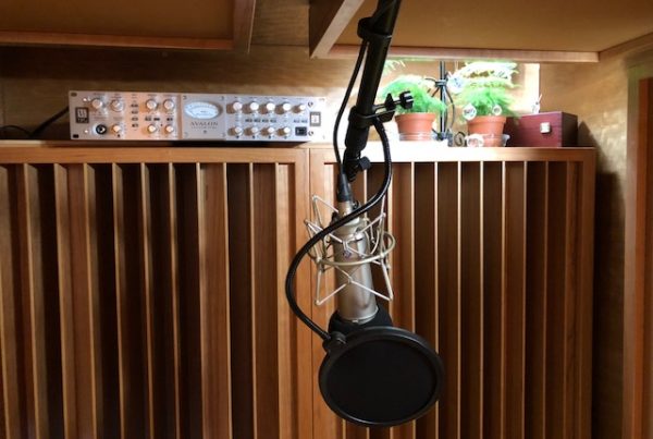
Quadratic diffusers can be used alone but the best way to achieve good results is to use multiple panels, side by side. A quadratic diffuser that is placed vertically, will diffuse sound energy back into our rooms in a horizontal, fan-like array and a diffusor place horizontally in our room, will spread sound energy out that enters it in a vertical, fan-like array. With both vertical and horizontal diffusers, one can have a two dimensional diffused sound field.

Formula For Well Depth
There is a formula for calculating the number of wells or troughs we need to use and what those wells or troughs depth dimensions need to be. The trough depth = the trough position squared mod N where N equals the number of wells and is a prime number. The squared portion of the equation determines the phase shift introduced by each of the wells and the mod operator keeps the shift within the range from 0 to 360 degrees. Raising a number to a power is known as a quadratic operation. Applying the modulus operator divides a number by the modulus and only keeps what’s leftover, known as the residue. This explains why the design is called a Quadratic Residue Diffuser, or QD diffuser for short.
Formula For Well Width
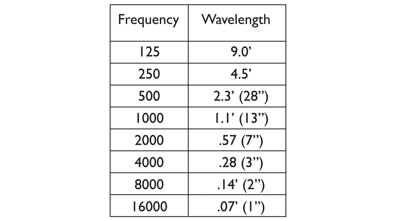
The width of the wells determines the high frequency (HF) cutoff frequency, where the width represents one half-wavelength. This is only for the incoming signal straight-on. For other angles of incidence, the HF cutoff is decreased, falling to zero for a signal striking from side-on. The period width has to at least equal the wavelength of the lowest frequency diffused. Software is available to assist one in the calculations. The prime number or frequency response you choose is based upon the distance from the room boundary surface to your ears.
Here’s a video I made showing how to put together one of our DIY quadratic diffuser kits:
Diffusion Limits
Below the design frequency, diffusion no longer occurs, but it is generally accepted that scattering is available down to one octave below the diffusion limit. For diffusion to occur, the wavelength of the lowest frequency diffused must be no larger than the period width of the panel. If this rule is not met, then the lowest frequency diffused is the frequency that does fit into the period width. This frequency is referred to as f period, and the new scattering limit becomes one octave below this.
Seating Distance
For the interference patterns to fully develop into a diffuse field, it is recommended that the minimum seating distance be three times the longest wavelength diffused. Diffused wavelengths need time to form completely before they reach the listening position. If one is seated too close or has the diffusor too close to the speaker or sound source, the diffused wave does not have time to properly form and you can have image shifting.
Diffusion Lobes
Diffusion lobes are created when a number of repeats of a periodic surface are placed together in a sequence. For multiple QD panels, the number and angle of the diffusion lobes vary with the panel order and panel width, and the frequency and angle of incidence of the incoming wave. For a signal straight-on, there are usually three lobes at the design frequency, and at the HF cutoff frequency, there is often the same number of lobes as there are wells.
Diffusion Process
As the angle of incidence is increased, starting frequencies for each of the lobes decreases slightly for lobes on the same side of the diffuser as the incoming signal. Lobes on the other side shift to a higher starting frequency by a larger amount. The angle of the lobes also changes, as does their relative angular spacing. In addition, the apparent wavelength of the signal changes as far as the wells are concerned, leading to a lowering of the HF cutoff frequency. When the angle of incidence reaches +/-90 degrees, the HF cutoff falls to zero, meaning no diffusion.

How Many Wells?
One can calculate what design frequency to use for any situation. As a general rule, one must use a prime number that can produce as many wells or troughs in the diffusion array as space permits. The more wells, the more frequencies diffused. A quadratic diffusor based on the prime number 23, will have 22 wells and 23 well dividers. If each well is 1″ wide and each divider is 1/4″ wide, we will have a diffusor that is approximately 28″ wide for each array. If we have a wall space that is 12′ wide, we will need 5 separate units placed side by side across the wall surface.
Quadratic diffusion is a powerful tool to manage room boundary reflections. It is a tool that can take the reflection and “break” it down into smaller “reflections” that can then be spread out into the room into vertical and horizontal directions without any change in the signals time signature. Build a diffusor that can diffuse as much energy as your space permits by using the free software available today.
In Summary
If you have any follow up questions on this subject please feel free to email me and I will be happy to help. Please message me at info@acousticfields.com. If you want to learn more about room acoustics please sign up for our free acoustic video training series and ebook. Upon sign up you will have instant access to the room acoustic training videos and ebook to help improve the sound in your studio, listening room or home theater.


How do I know if a quadratic diffuser is right for me/the room I am working with?
If I do decide to buy one of these diffusers how can I test its effectiveness/success?
T, Diffusion requires that you cover a certain amount of surface area depending on the usage within the room. For example, if you are using a room as a control room, you would install the correct diffusion, sequence across the total rear wall surface. If your room is a listening room, the front and rear wall would be diffusion candidates. In this case one diffuser would not be enough. To calculate the proper sequence, you must use distance from diffuser to listener and a few other variables depending on room dimensions. If you tell me more about your room by filling out the information in this link, I can assist you with the type, amount, and position.
Good evening Mr. Foley. I have a studio and the back wall is about 14 feet behind my back. I have 2×4 ATS bass traps in a standing position which leaves about 36 inc between them and the roof. I’ll like to add diffusers in that area. Is it necessary? what do you recommend?
Hi Allan, I will need more information about your room. Please fill out the information in this link: https://acousticfields.com/free-room-analysis/ Schedule a time to speak by phone.
I would like to know if placing quadratic diffusers that are based on different prime numbers side by side would have a negative impact on the sound energy?
F, Keep the frequency range the same throughout the wall surface.