An example of a Wave traveling through a room Dividing Acoustics of a Room: Understanding…
Dennis FoleyDecember 30, 2023

![]()
I am an acoustic engineer with over 30 years’ experience in the business. My technology has been used in Electric Lady Land Studios, Sony Music of New York, Cello Music and Films founded by Mark Levinson, and Saltmines Studios in Mesa, Arizona, along with hundreds of others.
© 2023 Acoustic Fields
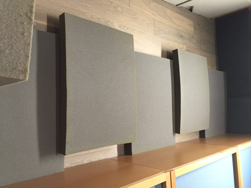

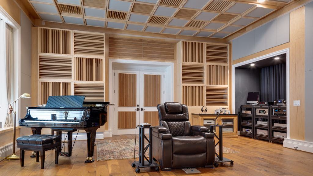

We use broadband absorption in the two most critical frequency regions in small rooms. Our Diaphragmatic absorbers, ACDA series, have…
Interesting web site and provocative introduction. Please check your copy for typos, otherwise nicely presented. I would like to see…
There is no such thing as soundproof anything especially carpet. Low frequency noise transmission requires a permanent construction fix with…
Hello Dennis! Our neighbors put a Ice Bath in their garage which is right below our bedroom and the Low…