Acoustic Design Project
Michael’s
Home Theater Room
Hot Springs, Arkansas, U.S.A.
Michael is the videographer that films all of our YouTube videos. Michael has shot more than 200 videos for Acoustic Fields. When Michael and I sat down in his room to listen to room sound quality, I could tell he was a critical listener. He pointed out the same parts within the song that I commented on to myself how good or bad they sounded. Michael could both hear and listen. To really enjoy music, you must have both skill sets. Michael enjoyed his current system and I could see that. I thought to myself,if he enjoys this level of sound quality, let’s figure out a way to enlighten this fellow about what is really possible.
Maximizing Surface Area Coverage
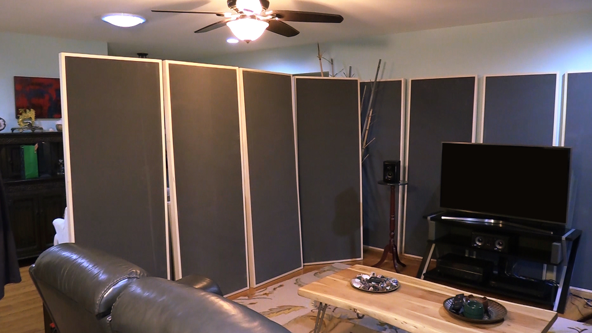
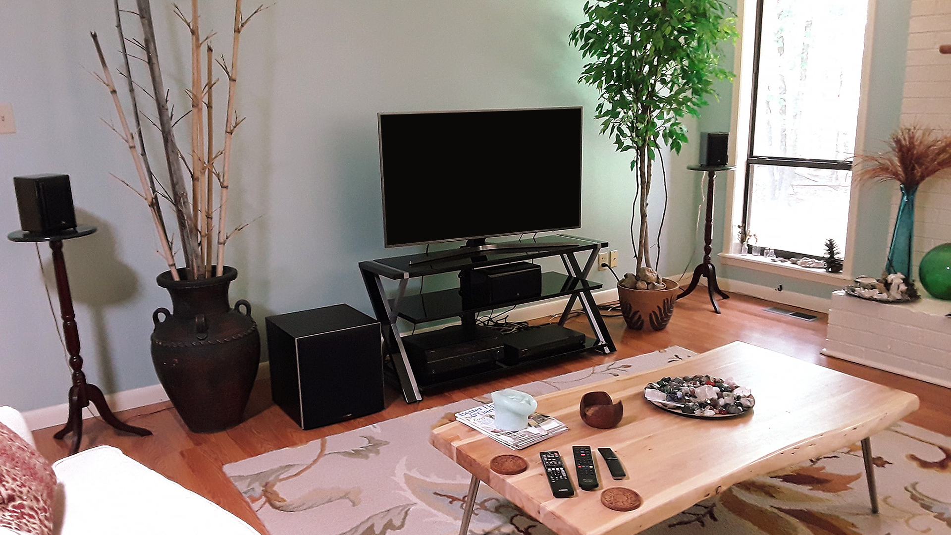
Let’s also do it in such a way that people could see the progression from proper positioning of speakers, proper positioning of treatment type and amount, along with an electronics upgrade. Michael’s room is a 7 part series that walks you through front, side, and rear wall middle and high frequency absorption, low-frequency absorption and proper setup for gear setup along with an electronics jump in power and processing. Come with us for the 7 – video series. Michael’s room is a small home theater project. It is a 5.1 system set up in a living room. The room is used for living and listening. We all know the difficulties with this type of dual usage room. Treating the wall surface areas requires large amounts of sound absorption and diffusion. Most clients are not willing to give up the surface area requirements that are necessary for proper acoustic treatment for the middle and high frequencies. Most clients are not willing to give up the space to treat low frequency issues.
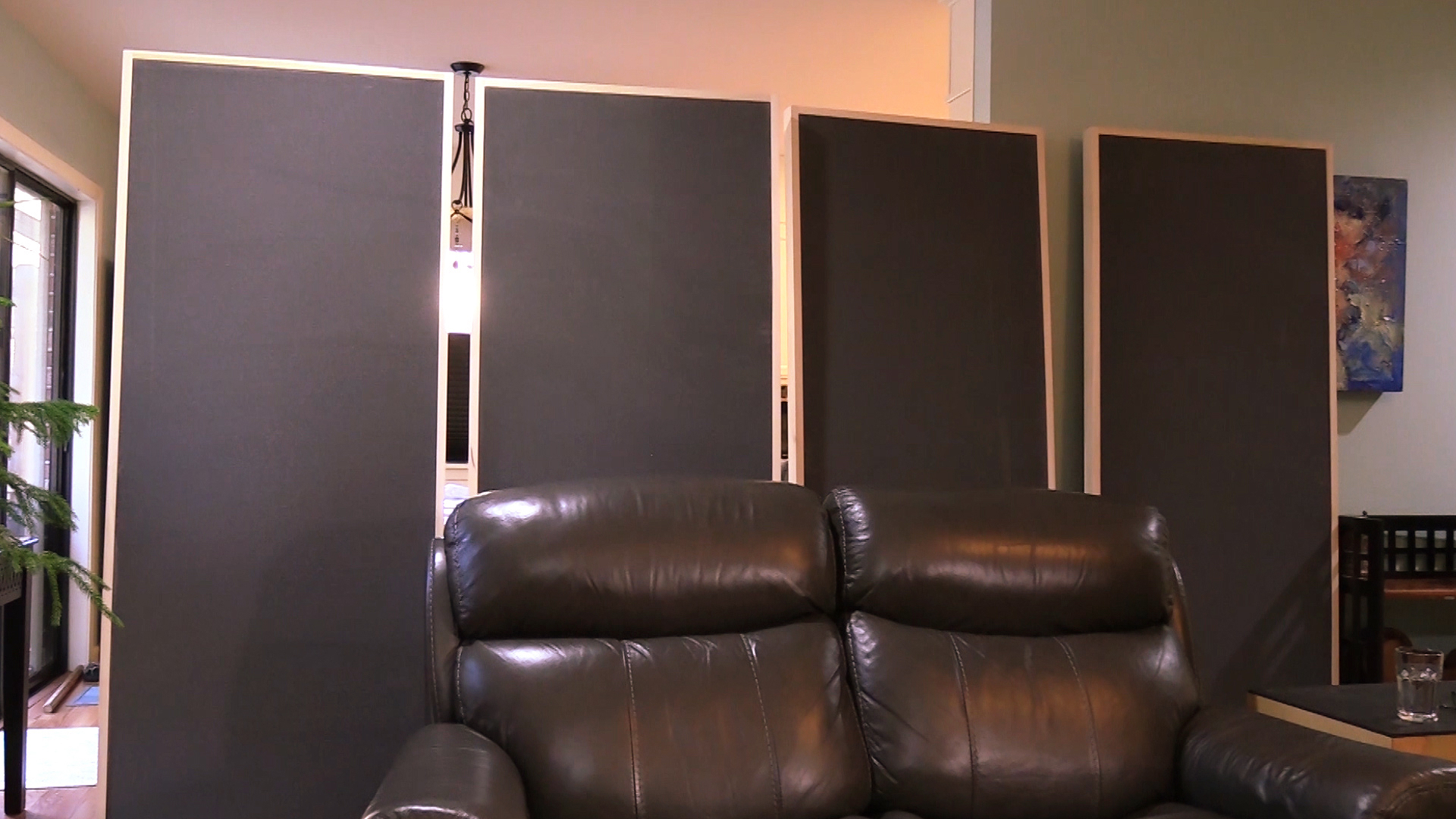
Low-frequency treatment requires that wall surface areas be treated to deal with the axial, tangential, and oblique modes that these surface areas create. In Michael’s room we focused on these issues and came up with a compromise that addresses the low, middle, and high frequency issues. As you can see in the photos, the room lacked sidewalls that were equal distance from the speakers. In order to compensate, we used our foam frame panels that were 72″ high. The panels were placed along each sidewall, the front wall, and the rear wall. This system provided a temporary fix to the wall reflection issues. The panels can be placed into position when one is listening to theater and then removed for the living usage. Our goal was to achieve as much surface area coverage within a system that could be removed and positioned along the front wall for storage. Our foam technology took 8 years to develop at a cost of 2 M. It has the best rates and levels of absorption for music and voice.


The Goal is Resolution
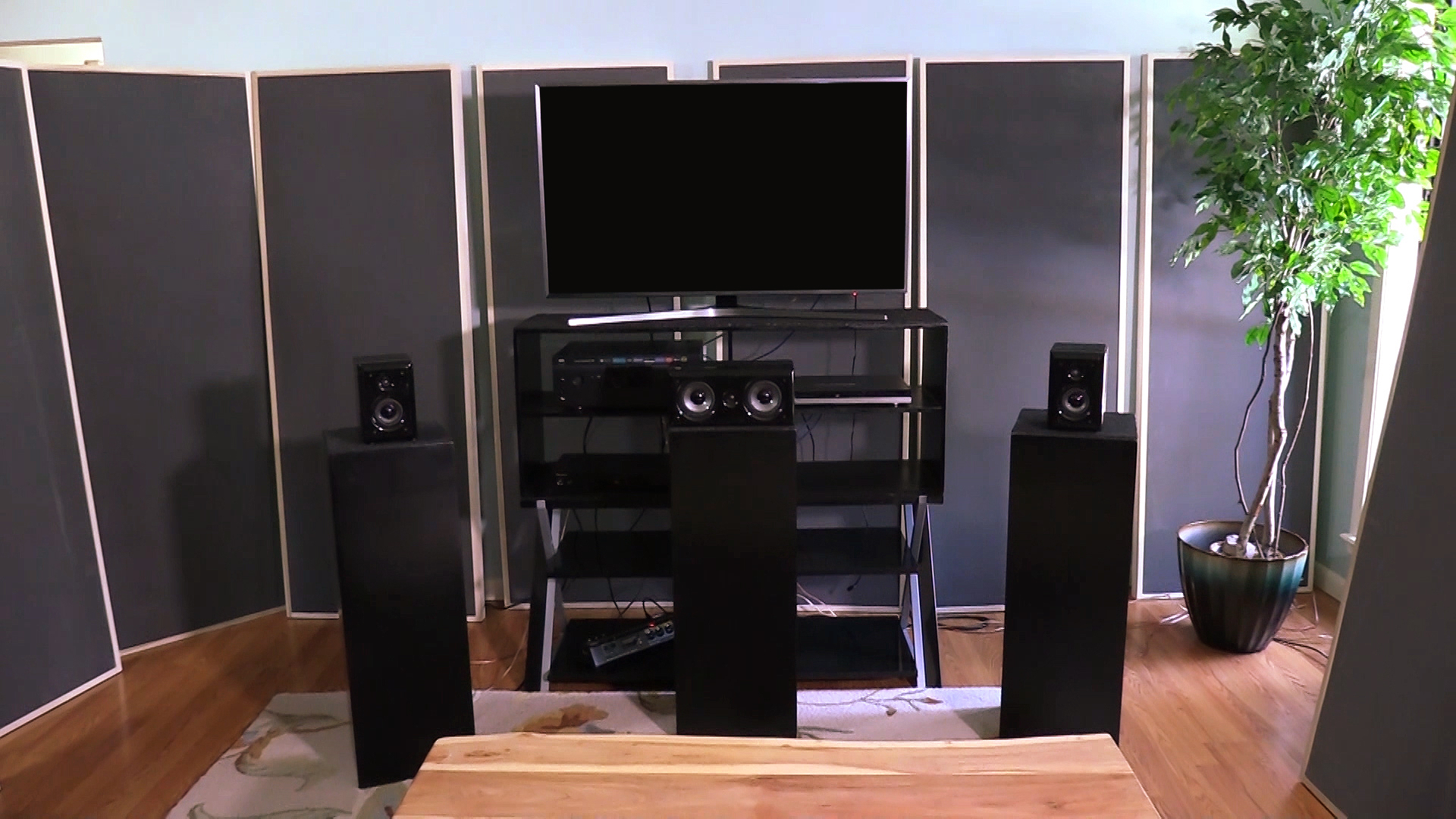
Low-frequency management was achieved in two major forms. First, I redesigned our current speaker platforms to produce more low-frequency absorption. With a depth of 12″, I had the ability to get down into that 30 – 50 Hz. region which is so critical for home theater presentations within small rooms. We were able to get this frequency range surface area coverage under each of the three front channels along with the two rear channels. I then looked towards the subwoofer platform to provide more surface area coverage. Remember with lower frequency absorption in small rooms, it is all about surface area coverage. We must have so many square feet of coverage to have an audible impact. I was able to increase the horsepower of the subwoofer platform by dividing it into two pieces, placing a piece on the subwoofer bottom to serve as a platform then another on top of the subwoofer. We coated each surface area with a durable mass loaded vinyl to resist usage issues with food and beverages. The five speaker stands along with the subwoofer platform allowed us to achieve “critical mass”.
We had reached the minimum square feet of coverage required for this room size and volume to give us a large audible improvement. I then turned my attention to the electronics. The existing speakers were fine. These 18 year old beauties sounded wonderful even after 18 years. Cable was a zip cord. Receiver was a low end consumer version that had bare wire connectors. With a zip cord as the speaker cable, the individual copper strands had to be wound around a bolt with a plastic cap for securing said materials. Not acceptable. Our goal is resolution, not more noise. After hours of searching for an amplifier that could handle spades, I decided to separate the amplifier and the processor into individual units. I found Emotiva in Tennessee to assist me with a separate amplifier and processor. We ordered all new left, right, and center channel speaker cables from Wireworld. The rear channel runs were 30′, not cost effective with higher end cables. I found some 8 gauge cable spool with a 100′ of cable run. I terminated the ends with spades.
Michael’s Room Video Series
[yottie id=”8″]

Acoustic Foam Panels
The most economical way to display our foam is to use our Foam Frame Panel. Our proprietary foam is not rigid enough to stand on its own. To alleviate this issue, we simply surround our foam with a wooden frame like a picture. This allows for the foam to be hung on a wall or in the case of Michael’s room, we stand the panels on the front side and rear walls. The frame can be painted or stained.The foam is grey in color. We can increase the thickness to allow for lower frequency absorption using this method.
Do you want to solve your room acoustic problems?
There’s no one size fits all when it comes to room acoustics.
Get your FREE personal room acoustics analysis by chief acoustics engineer Dennis Foley.


